
Bussey Bridge Disaster: Faulty Welds Explained
The following explanation, prepared by a gentleman who has made a special study of the cause of the disaster at Bussey Bridge, will make clearer the statement written for the Engineering News and published in the Globe Thursday morning. The statement in the Engineering News refers to the defective character of two hangers which were found to have been seriously rusted along the welds at the lower ends.
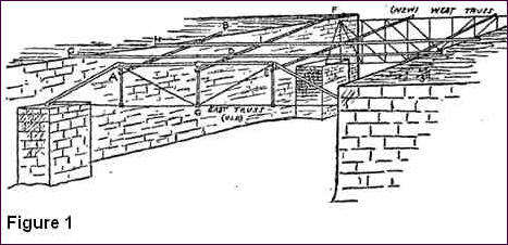
Figure 1 shows in outline the general arrangement of the bridge. It will be seen that the two trusses are connected by floor beams, upon which the two stringers are laid. Upon these stringers are laid the cross-ties and rails of the track, which are not shown in the drawing. Both floor beams and stringers are trussed; the rods, are, however, not shown.
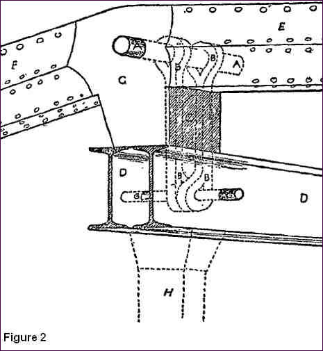
The locations of those hangers is shown (with diagonals and bracing removed) in Figure 2, where FF is the inclined end post and EE the top chord, each of which bears upon the end joint block CC. Through this casting passes the pin AA, and from this pin the floor beam, DD, is hung by hangers or stumps BB. The pin AA also passes through the upper loop of the hangers, and a pin, GG, passes through their lower loops and all through the two I beams DD, thus suspending the floor beam. The hangers, being inside the box-like casting, CC, it is evident that it was impossible to inspect or to paint them; a portion of the lower ends only, at BB, being visible. Under the floor beams is the post H, which, however gives little support.
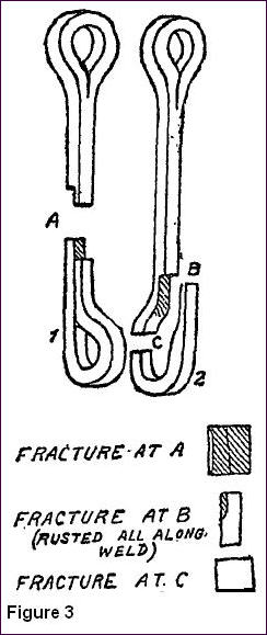
 The appearance of the broken hangers, with the fractured sections, is shown in Figure 3, where the rusted section is shaded. It will be seen that A is evidently an old break, being almost entirely eaten across by the rust, besides being split up from the eye along the line of the weld. The other link is more perfect, C being evidently a fresh break, although it is rusted and split along the weld to B. The form of these links is such as to cause what is called “eccentric loading,” because the center of the lower eye is not in the line of the pull, the lower loop acting precisely as a hook would, thus bringing a great bending strain, which would naturally cause it to break at C. It is the pieces numbered 1 and 2 that disappeared soon after the accident and which are reported to be in the possession of the “Engineering News.”
Published in the Boston Daily Globe on March 19, 1887.
 View Printer Friendly Version
 Email Article to Friend
